
Identify the system
Brand, exact implant system and precise prosthetic platform.
Provisional abutments · digital workflow
A provisional abutment is not an isolated component in a CAD workflow. The implant system, platform, scan body actually used, TECH or LITE library branch, -06/-07 indication and selected HIGH, MID or LOW cementation height must all correspond.
Workflow
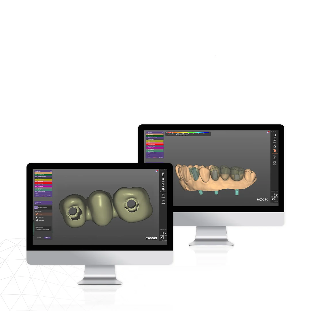
The most common error occurs when the physical component and digital library are treated as separate systems. A correct workflow keeps the entire chain consistent.
Brand, exact implant system and precise prosthetic platform.
The laboratory must know which scan body was actually present in the mouth or model during acquisition.
TECH follows IPD scan-body geometry; LITE follows explicitly supported OEM or third-party scan-body geometry.
A single crown, bridge or multi-unit provisional restoration determines the indexing requirement.
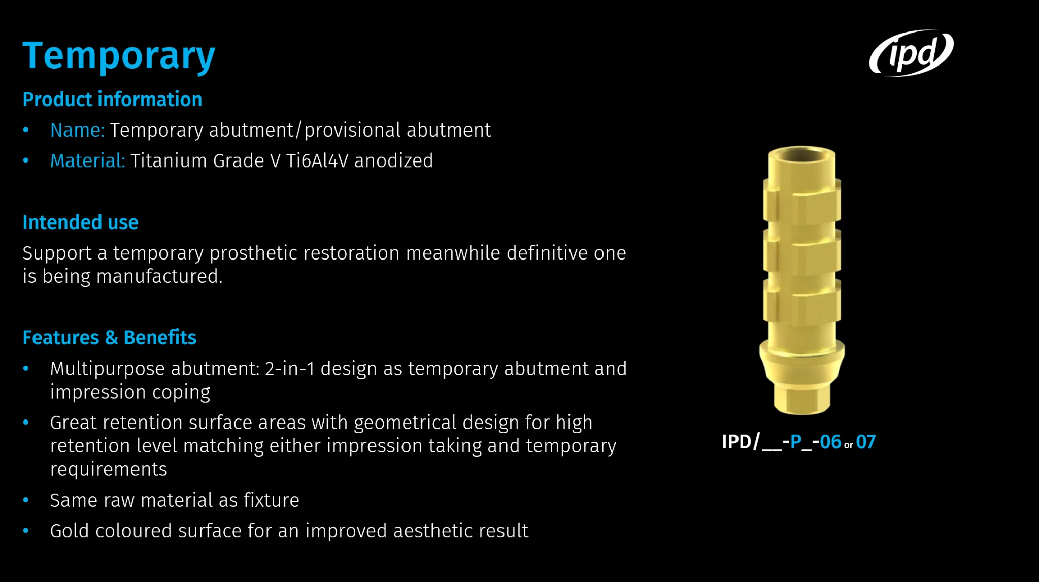
-06 is indexed for crown indications; -07 is non-indexed for bridge indications.
This is the library cementation height, not the gingival height.
The library defines the seating and support geometry for the crown or bridge.
If necessary, shorten the physical provisional abutment to the same height selected in the library.
Indexing and indication
The anti-rotational geometry is intended for situations in which both CAD and the physical component must preserve a specific rotational orientation. A typical example is a single crown.
The rotationally free option is intended for multi-unit restorations where a common path of insertion across multiple implants or abutments is the priority.
Cementation height
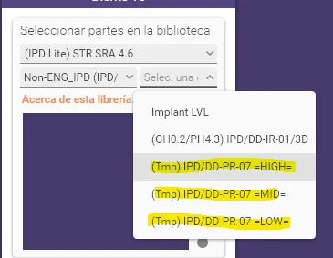
The provisional-abutment library provides three cementation heights. The selected level determines where the software prepares the restoration interface. When MID or LOW is selected, the physical abutment must therefore be shortened to the corresponding level if required.
Suitable where sufficient occlusal space is available and a taller retentive surface is desirable.
A compromise between retentive surface area and available space. The physical component is adjusted to the selected library level.
For limited vertical space. It requires careful agreement between the virtual component and the component actually shortened physically.
CAD software
| Step | Exocad | 3Shape |
|---|---|---|
| 1 · find the library | Selection is organized by connection and platform diameter. | Selection is organized by brand and connection. |
| 2 · assign the scan | Select the exact corresponding Scan Body. | Select the exact corresponding Scan Body. |
| 3 · select the component | Crown or bridge option according to the indication. | Crown or bridge option according to the indication. |
| 4 · select the height | HIGH / MID / LOW. | HIGH / MID / LOW. |
| 5 · design | Continue with standard implant-restoration design and STL export. | Continue with standard implant-restoration design and STL export. |
If the clinical scan was acquired with a scan body explicitly included in the LITE library, the laboratory can continue to an IPD component without replacing the acquisition geometry with another scan body. What matters is the exact match between the scan body, platform and target component.
Common questions
They are three library cementation heights above the prosthetic interface. They do not represent the gingival height of the abutment. If MID or LOW is selected, the physical provisional abutment is shortened to the corresponding level according to the instructions before being joined to the designed restoration.
In IPD catalogue logic, -06 is the indexed option for a single crown and -07 is the non-indexed option for a bridge or multi-unit indication. Always verify the exact platform and current catalogue or library.
Yes, but only if the exact scan body used is explicitly supported in the corresponding IPD LITE library for that system, platform and target component. The CAD software must use the exact scan body that was physically used during scanning.
Not automatically. If the selected LITE library supports the original scan body and target provisional abutment, the laboratory can continue from the existing data. If the scan body is not supported by the library, its geometry must not be substituted simply because another scan body looks similar.
In Exocad, the workflow is organized by connection and platform diameter, followed by scan-body and cementation-height selection. In 3Shape, selection is organized by brand and connection, followed by the scan body and cementation height.
For product families listed in the catalogue as Temporary abutment / Open tray coping, the same component can serve as a provisional abutment with the occlusal screw and as an open-tray impression coping with the long coping screw.
The system and platform, scanning level, scan body actually used, correct TECH or LITE branch, crown versus bridge indication, corresponding -06 or -07 option, selected HIGH/MID/LOW height and physical agreement between the component and the design.
Next verification step
Send the system and platform, a screenshot or reference of the scan body used, CAD software, intended indication and provisional-abutment reference. We will help verify the correct library branch before design.