
Can be used now
Mucosa and ridge anatomy, approximate prosthetic space, preliminary tooth setup, denture-base extension, relationship to the antagonist and communication about the future design.
Decide first, select components second
A practical decision hub for clinic and laboratory: what can be done from a conventional STL, when a new implant-position transfer is required, how to use KA-CL-14 and when a bar adds genuine value.
This is not a universal clinical protocol. Always verify the exact implant, platform, gingival height, tightening torque and permitted workflow in the current IFU and documentation for the relevant system.
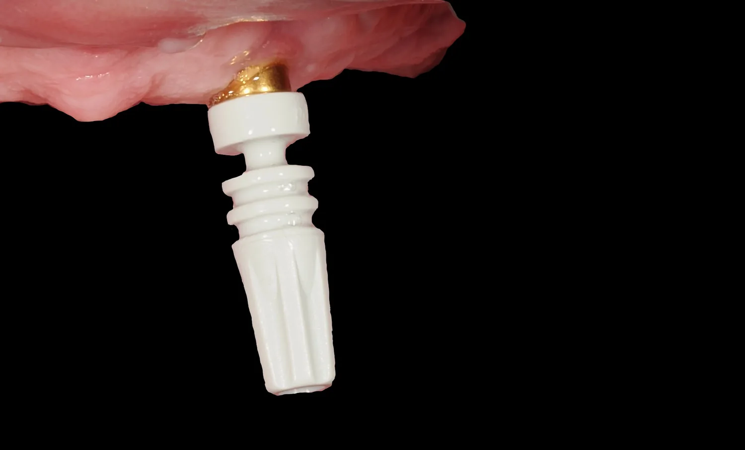
Starting situation
Such a dataset is useful, but it does not contain a complete library-based implant reference. It is therefore important to separate anatomical information od implant coordinates.
Mucosa and ridge anatomy, approximate prosthetic space, preliminary tooth setup, denture-base extension, relationship to the antagonist and communication about the future design.
The exact 3D implant axis and connection, definitive analog position, an accurate bar or an implant-supported framework based only on the visible coronal part of the fixture.
An anatomical model can be printed for planning. An implant working model only becomes meaningful after validated position transfer; in the digital PSD pathway it uses PS-AR-00/3D.
Who is responsible for each part of the chain
The laboratory does not take over clinical implant identification or treatment indication. Its strength is to define clearly, before fabrication, which data are required and which prosthetic pathways are technically feasible from those data.
Identifies the manufacturer, system and platform of each implant from documentation or the implant card.
Assesses the soft tissues, gingival height, healing and clinical conditions for the selected abutment.
Seats the correct components and applies the tightening torque specified for the exact reference in the current IFU.
Performs the intraoral scan or conventional impression and records the antagonist and bite.
For a bar, clinically verifies seating, passive fit, hygienic access and finally the function of the completed prosthesis.
Checks whether the supplied data truly contain a validated implant or PSD reference rather than anatomy alone.
Evaluates prosthetic space, tooth setup, path of insertion, hygienic access and required framework thickness.
Works with the clinician to determine whether a direct PSD pathway or a primary CAD/CAM framework is more appropriate.
Selects the correct CAD library, verifies scan-body matching and decides whether a physical working model is needed for laboratory completion.
Completes the framework, housings and processing, and prepares clear documentation of the components used for the clinical team.
Main decision point
The number of implants alone does not answer the question. Geometry, prosthetic space, hygiene, required stability and the need to create a new common retention axis are what matter.
Prefer this as the simpler starting solution when implant positions and the common path of insertion are favourable and the attachments fit within the planned retention concept.
Fewer structural layers and less demand on vertical space.
Easier access to individual attachments for maintenance and hygiene.
Digital transfer: implant-specific PSD → KA-CL-14 in scan configuration → PSD library → PS-AR-00/3D where required.
Consider this when the framework solves a genuine geometric or functional problem: divergent axes, the need for a new common retention axis or greater stability, provided that sufficient prosthetic space and hygienic access are available.
First transfer the implant or selected abutment level accurately for bar design.
Manufacture the framework and verify its passive seating independently.
KA-CL-14 is used only afterwards, for digital transfer of the PSD sites on the completed framework.
Pathway A · three possible transfer routes
The retention concept remains the same, but the way the geometry is verified and transferred can be digital, conventional or hybrid. The choice depends on the available data, confidence in the implant-level transfer and whether the gingival height of the future PSD / Locator-compatible attachments is already known reliably.
If the definitive PSD attachments have already been selected and seated clinically, their actual positions can be recorded with KA-CL-14 in the scan configuration and processed using the corresponding PSD library.
Control point: correct attachment reference, gingival height, complete seating of KA-CL-14 and correct library matching.
Once the definitive PSD attachments have been selected and seated, their positions can be transferred with an elastomeric impression using KA-CL-14 at the impression-coping length, creating a stone working model with PS-AR-00.
Control point: stability of the coping in the impression and correct connection of the analog.
If implant-level IOS data are available but the definitive PSD height is not yet known, an implant-level model can be printed with system-specific digital analogs. The laboratory creates a verification jig on suitable rigid reference components, for example Ti-bases, and the clinician checks intraorally whether the model reproduces the relative implant positions without a clinically significant discrepancy.
After successful verification, the correct PSD attachment gingival heights are selected clinically, the attachments are seated and their definitive attachment-level position is transferred with an elastomeric impression.
the implants have sufficiently different axes that individual attachments do not create a favourable common path of insertion;
a new, planned common retention axis needs to be created;
implant distribution or the prosthetic plan requires greater stabilisation and rigid splinting;
there is sufficient vertical and horizontal space for the bar, PSD attachments, housings and prosthesis material;
the framework can be designed with adequate hygienic access;
a verified implant-position transfer is available for fabrication of a passively seating framework.
the implants have favourable axes and four individual PSD attachments provide a functional path of insertion;
direct PSD already provides the required retention and stability;
vertical space is limited and the bar would reduce space for teeth or denture-base material;
the bar would reduce hygienic access;
adding a rigid framework would not solve a specific geometric or functional problem;
the simpler solution is easier for the patient to maintain and keep clean.
An anatomical STL shows space and future prosthetic anatomy, but without a reference transfer it does not yet show the exact 3D implant axes. The definitive decision about a bar should therefore follow acquisition of these data.
the implant, system and platform at every position;
the exact 3D axes of the implants / working abutment level;
the planned tooth setup and volume of the future denture base;
available vertical and horizontal prosthetic space;
the target common path of insertion;
realistic hygienic access around the framework.
Pathway A · direct PSD
Once the implants and platforms are confirmed and the direct PSD solution has been selected, attachment positions can be transferred digitally or conventionally.
Select according to implant, platform and gingival height, and seat correctly in the clinic.
For the digital pathway, use the scan configuration. For the conventional pathway, use the impression-coping length.
Capture all four positions, sufficient mucosa, the antagonist and a reliable bite record.
Digital: PSD library and PS-AR-00/3D where required. Conventional: PS-AR-00 in the stone model.
KA-CL-14 uses irreversibly shortened lengths. For an independent control impression and digital scan, the cleanest methodology is to keep one set at the impression-coping length and a separate set at the scan length. Sequentially shortening the same component after the impression is mechanically conceivable, but it removes the option to repeat the impression without a new component; without explicit manufacturer confirmation, we therefore do not treat it as the preferred validation protocol.
A physical model is not the goal of the workflow. It is a tool. Print one when it makes verification, processing, communication or subsequent manual laboratory steps easier.
For preliminary anatomy, the current STL can be printed without implant analogs.
For a definitive PSD working model, the position must come from KA-CL-14 + library matching and the PS-AR-00/3D digital analog.
In a fully digital, validated workflow, the physical model can be omitted if the laboratory does not need it for any verification or manual step.
| Model | What it contains | What it is for | What it cannot do |
|---|---|---|---|
| Anatomical model | Mucosa, ridge, any remaining teeth, antagonist | Space, setup, denture base, communication | Exact implant axis and analog position |
| Stone PSD model | KA-CL-14 as impression coping + PS-AR-00 | Conventional laboratory workflow | Not the digital-analog pathway |
| 3D-printed PSD model | KA-CL-14 scan + library + PS-AR-00/3D | Digital working model and laboratory completion | Does not correct a poor scan or incorrect matching |
3D printing · Validation Master · outsourced production
The most important distinction is between calibration of the printer itself od and validation of digital-analog seating. The first belongs to the operator of the printer. The second links the CAD library, offset, specific printing process and the real PS-AR-00/3D analog.
The laboratory is responsible for operating calibration of the printer according to the manufacturer, the correct resin and profile, post-processing and the IPD validation test. It prints the Validation Master, verifies the actual analog and uses the result to select the corresponding offset / library.
If the model is printed by an external production centre, the laboratory cannot calibrate that printer remotely. The centre controls the printer, resin, profile, exposure, layer settings, orientation and post-processing. The laboratory must, however, know the result of the validation print and select the correct CAD tolerance according to the actual seating of the analog.
If an external centre creates the model from scans and also performs the printing, confirm before the first case that it can work with the exact PSD / IPD digital-analog pathway and that responsibility for selecting the offset is clearly defined. A generic “implant model” service does not by itself confirm compatibility with PS-AR-00/3D.
The same validation logic applies regardless of supplier. The printer type or production technology alone does not confirm the correct IPD offset or the accuracy of the functional socket for the digital analog.
An anatomical model, or a functional implant PSD model with a socket for PS-AR-00/3D? Validation Master addresses the second category.
Send the corresponding validation STL / Validation Master first and request the same manufacturing standard that will later be used for the working model.
Printer, resin, material profile, layer settings and post-processing are managed by the centre. Its internal hardware calibration is not the laboratory’s task. For ASIGA printers, the manufacturer recommends regular platform checks; for the PRO 4K, for example, approximately once a month or after 20 prints. This is machine-service calibration, however, and does not replace the IPD Validation Master used to verify digital-analog seating.
Test the master physically with the analog. The correct position allows complete, stable seating without excessive force, resin deformation or unwanted play.
Based on the result, the laboratory selects the corresponding IPD library variant or offset. Only then should the final working model be exported.
State in the order that this is an implant working model for the PS-AR-00/3D digital analog and that manufacturing should follow the previously validated printing chain.
If the centre changes printer, resin, profile or a major post-processing parameter, revalidation is appropriate before a critical case. Leave orientation and supports to the centre’s validated manufacturing protocol.
The analog must reach its full seated position without excessive force and without play. If it does not, do not “eyeball” a correction of the socket; return to cause identification and the Validation Master.
Revalidate with the first printer + resin + profile + post-processing combination, after changing production centre or key parameters, after printer servicing, and whenever analog seating begins to differ from the previously validated state.
If the same printing chain has already been validated, parameters have not changed and ongoing checks remain stable. Validation Master verifies a production process; it is not a mandatory model before every case.
when printing only an anatomical model without a precision socket for a digital analog, or when no physical model is produced. Validation Master also cannot correct an inaccurate intraoral scan, incorrect matching or the wrong library.
Printer hardware / process calibration belongs to the printer operator and follows the printer and resin manufacturer’s instructions. IPD seating-validation check verifies whether a specific CAD socket and offset work in the real production chain. With outsourcing, this is therefore a collaboration: the centre prints the validation sample, the laboratory or centre with access to the test analog verifies seating, and the laboratory uses the corresponding library variant.
With outsourced manufacturing, confirm in advance that the supplier uses a stable, validated printing chain. Printer or resin brand alone does not confirm a specific IPD offset; the decisive control is the real seating of the analog in the validation sample and working model.
Practical data hand-off
The best laboratory workflow is not to ask the clinic simply to “send a scan”, but to define the exact data package in advance according to the selected pathway.
Manufacturer, model, platform and position of all four implants. Ideally the implant card, surgical record or photographs of the labels.
The relevant arch with a validated reference, the complete relevant edentulous segment and enough stable geometry for verification.
A separate antagonist scan and usable interocclusal record. Existing data can be retained if they can be registered reliably.
Clinical information on gingival height, soft tissues and available space. The laboratory compares this with the planned tooth setup and framework.
Occlusal and lateral photographs can quickly reveal spatial or hygiene problems that the mesh alone does not explain.
Confirm: direct PSD vs bar, target path of insertion, digital vs conventional transfer, and whether a physical working model will be needed.
Quick check before manufacture
Are all four implants and platforms identified unambiguously?
Do we have an exact implant or PSD reference, rather than only an anatomical STL?
Has it been decided whether the attachments will be directly on the implants or on a bar?
Is the prosthetic space for the attachment, housing, prosthesis material and any framework known?
Has the correct KA-CL-14 function and length been selected?
Do the scan body, library and analog belong to the same workflow branch?
Is it defined in advance who will verify seating, occlusion, retention and hygienic access, and at what stage?
RELATED MANUALS
The decision hub deliberately does not duplicate detailed processing, retention and framework steps. Once the pathway is chosen, the user opens the dedicated workflow.
Common questions
Important information for use
PSD attachments, housings and accessories must match the implant system, platform and selected retention protocol.
I am a healthcare professional within the meaning of Section 2a of Czech Act No. 40/1995 Coll., on the Regulation of Advertising. I confirm that I am authorised to access pages intended for healthcare professionals.